

PCI Express improves on PCI by using high speed multiple lanes. A single lane consists of a transmit and receive pair, which operate in full duplex at 500MB/s. The lanes can be grouped together in multiples to form links. For example a PCI Express x16 slot would have a single link made up of 16 lanes.
PCI Express connectors are available as x1, x4, x8 and x16 and offer the following bandwidths: -
| Links | Bandwidth |
|---|---|
| x1 | 500MB/s |
| x4 | 2GB/s |
| x8 | 4GB/s |
| x16 | 8GB/s |
Slots are not always what they seem
The PCI Express standard is very flexible. A plug-in card can be fitted to any slot which is at least as large as it is. For example a x1 card will function in a x1, x4, x8 and x16 slot.
Slots don’t have to be electrically wired with the full compliment of lanes, as long as the electrical power and ground connections are tracked in. It is common for products to have x8 or x16 physical slots which are only x4 and x8 respectively. For this reason, it is always necessary to read the fine print of the product specification.
A PCI Express card will negotiate and use what lanes are available on the socket it is plugged into. However, the function of a card could be severely impaired if it is running on less lanes that it was designed to make use of. This is an important consideration when using high performance peripherals such as RAID and graphics cards.
Graphics and Server Architectures
All motherboards and Single Board Computers (SBCs) are based around specific chipsets. Typically the chipset is made up of two large scale devices named the North and South bridge. These devices interface with the processor and all of the subsystems on the board.
Graphics based chipsets are optimised for multimedia use where high performance video is required and nearly all have a x16 link optimised for graphics card use. Some high end gaming motherboards have two or more x16 slots that support Nvidia ‘SLI technology’. In addition to the dedicated graphics link, four lanes are available to be configured as the board manufacturer wishes. Typically these will be utilised as four x1 board slots. Non-graphics cards should not be used in a x16 graphics slot unless the card manufacturer specifically states compatibility.
Server chipsets are designed to service high throughput plug-in cards such as RAID and fibre channel controllers. They do not have dedicated graphics links, so more lanes are available to be configured as the board manufacturer wants. This more flexible approach means that boards such as the Intel server motherboard S5000xxx are available in a number of variants with different PCI Express connector options. However, the maximum link size is usually limited to x8.
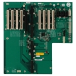
Single Board Computers and PCI Express - PICMG
The international organisation which controls how Single Board Computers and backplanes are designed is called PICMG http://www.picmg.org/ . The latest version of the standard (PICMG 1.3) defines two separate classes of product which deal with graphics and server based architectures. The two standards are not interchangeable and it is possible to damage products if SBCs and backplanes from either class are mixed.
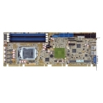
Most SBCs on the market are graphics class. This is due to the products being based on desktop processors and chipsets such as the Intel Core 2 Duo. Desktop chipsets also have more integrated features which make them a more cost effective option.
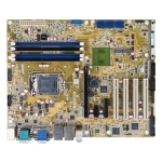
Server class SBCs are based on server chipsets and processors such as the Intel Xeon or an AMD Opteron processor.